As promised, here's my tutorial on how I'm wiring my smartgun front switches to run the effects board, for the benefit of anyone who'd like to try the same.
First things first, a shameless plug. My effects board was designed and made by Tim Shilling at ASP Engineering (
www.aspeng.com) and is the result of months working with him to fine-tune the design and especially the sound effects. I think he did a pretty damn good job, and I wouldn't put a plug in for him if I didn't. I recommend this effects module to anyone who is putting together an M-56 and wants to "bring it to life."
That said, on to the tutorial!
Electronics 101
These are all very simple, serial circuits, so if you know how to strip wire and solder a switch contact, you can do this mod. Like wiring a light bulb, it does not matter what side of a switch you connect the + and - wires to; it will still complete the circuit regardless of which direction the current flows through it.
The Switchgear
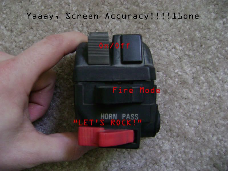
This is a Left-Hand Switchgear from a Kawasaki GPZ-750 motorcycle, used to make the front-grip controls on the smartgun. When you get yours, it'll probably have the original wiring harness; mine was pretty ratty-looking, so I've removed it and will build a new harness myself.
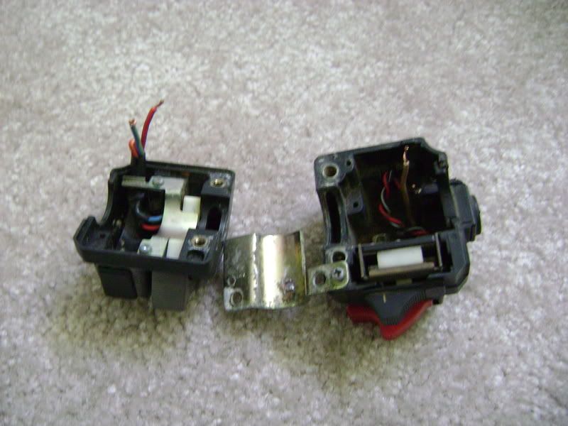
This is what your switchgear will look like opened and gutted.
FRONT SHELL
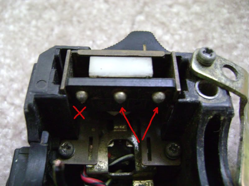
This is the underside of the first selector switch, the horizontal black one. You will see three wires attached to the switch; mine were corroded and about to fall off on their own, so I just removed them in order to solder new wires directly onto the switch contacts.
The switch has three positions, and three contacts: left, right, and common. In the neutral center position only the common contact is engaged, while pushing the switch to the left or right engages the common and the respective left or right contact. I want to set pushing the switch fully to the right to engage the effects board's "burst mode," so the center and right contacts will be wired to that function. The left contact will not be used.
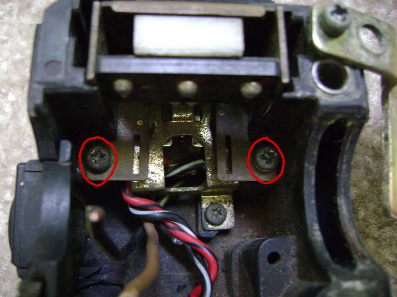
The selector switch is held in place by two screws, seen here, and is easy to remove if you need to get to the red "fire" switch beneath it. You may need to do exactly that to clean the contacts of the switch - mine were gunked all to hell and didn't work until I cleaned them. Fortunately, the switch body for the red switch has holes on each side where you can see the contacts engaging as you play with the switch. You can use those holes to clean them.
To remove the red switch, you will need to remove the third screw in that picture and then unscrew the red switch cover from the switch post itself.
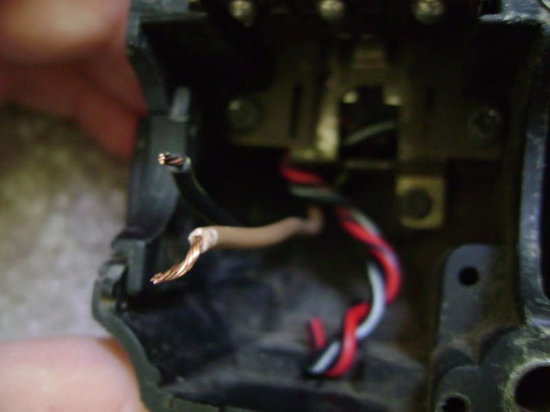
The wiring for the red switch is a little more complicated, but not much. The switch actually rocks both ways, so it has two sets of contacts. Pushing the switch UP engages the black/red and black/white wires; I want pushing the switch DOWN to "fire" the gun, so I have pushed the other wires out of the way leaving the
brown and
black/yellow wires exposed. These are your fire switch wires.
BACK SHELL
The second selector switch - the vertical gray one - is pretty straightforward, and it's what I'm using for my on/off switch for the effects board.
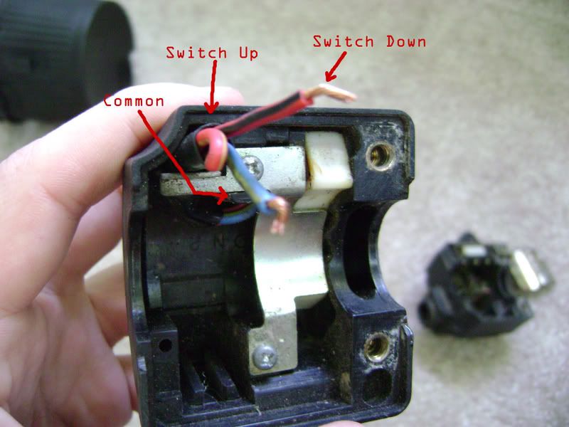
This switch has two positions and three contacts: Up (towards the user), Common, and Down (away from the user). In either position, the respective contact as well as the Common are engaged. I want to turn the effects board on by pushing this switch down, so I've bent the Up wire back out of the way. The remaining two wires are the ones you'll wire to your battery. Just clip the wires from the power switch that comes with the effects module - same as you will do with the switches for the other functions already mentioned - and connect those two wires to the ones in the switchgear.
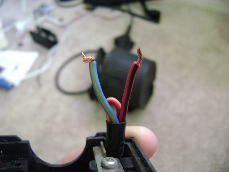
Here is a close-up view of the on/off wires: blue/yellow and red/black.
 DV-9 BATTERY and CABLE HARNESS
Last but not least, here's a closeup of the battery contacts. To save space on the gun and allow myself to use a bigger speaker and amp, I've decided to put the amp on the vest, and that means running the speaker wire through the cable harness that runs along the steadicam arm, through the battery, and into the gun. That may sound complicated in writing, but as circuits go, it literally doesn't get any simpler than this.

The screen-accurate plugs to use are 1/4" Mono audio plugs, which makes things even easier. Looking at the back of the plug (or jack) you will see just two contacts: a center contact, which is the tip of the plug, and an outer contact, which is the shaft of the plug.
All you have to do is make sure that the input to the speaker (or the output from the amp, depending on how you look at it) is wired to the same contact on both the vest and gun sides of the harness - i.e., if the line out from the amp is on the Center contact coming from the arm, the speaker's input needs to be wired to the Center contact on the gun side. And of course, make sure the battery's plugs are wired center-to-center and outside-to-outside.

Hope this helps! Feel free to send me a PM if you need more help with any of this, good luck, and HAVE FUN!
_________________

CPL Sean Maio A01/TQ2.0.72156E1
Public Relations Division (Temporary Cross-Assignment)
M-56 Smartgun Operator, A/3Btn, II CMEF, USS Sephora