The discussion of the Alien series of films and the props used in them is the aim, but if it's got Big Bugs and Big Guns, then they are welcome too!


Post new topic Reply to topic  [ 28 posts ]  Go to page 1, 2  Next
Author Message
 Post subject: My First Pulse Rifle
PostPosted: Wed Aug 04, 2021 4:27 am 

Country: United States
Hi everyone.

I've lurked here for a little while now, drooling over everyone's builds. I just finished my first PR build, and only really found this forum at the end of it. I wasn't going to post it, because my build isn't anywhere near as impressive as all of yours. But now that I'm done, and starting to work on my next one, I figured what the hell - maybe it'll help some other newbies feel like they can do it too if they see a build that's not as dauntingly good as everything else here.

When I say newbie, I'm describing how I was when I started my build - I loved Aliens a ton, but had never made a physical prop of any kind, knew nothing about guns / airsoft / etc, and couldn't find any of the commercially available PRs because they all seemed to be gone before I realised they existed.

My apologies in advance for being too wordy - but I did want to write down all of the mistakes I made during the build, so that I can avoid them in my next one. Using this thread as a vehicle to do that seems like a way to make me do it thoroughly, and to help others avoid making the same mistakes. Also worth noting that a lot of this thread will be me fumbling through figuring out how to do something that I suspect most of the people here know how to do "the right way", which I'm now looking forward to learning.

Anyway, enough preamble.

Back at the start of 2020 I'd bought a Prusa i3 Mk3 3D printer, and was cruising Thingiverse when I found a model for a PR. Not long after, when Covid quarantine hit and I had a bunch of spare time, I thought it'd be fun to try to print it. But once I'd printed a few of the pieces, I realised I wasn't super happy with the model. The pieces didn't line up very well, and I couldn't get superglue to hold it together well enough to not break apart when you waved it around (which my kids really wanted to do).

Around the same time, I found Majenko's PR counter, and that made me immediately want to put electronics in the PR. The model I'd found didn't have any room for them, nor did it have a working trigger. Screw it, I thought - I've got a bunch of time now that I'm stuck at home, maybe I can learn Blender and model it myself.


Top
 Profile  
Reply with quote  
 Post subject: Bad Dreams
PostPosted: Wed Aug 04, 2021 4:31 am 

Country: United States
So I watched some Blender tutorials and started trying to model. I figured the stock looked like the easiest place to start, being simple and mostly flat planes. At the time I wasn't worrying much about matching the design exactly, I figured I'd be able to rescale things later. By the time I was done with it, I'd become comfortable enough with Blender's UI that I was starting to enjoy it.

Attachment:
Stock.jpg
Stock.jpg [ 54.06 KiB | Viewed 3671 times ]


After that I moved to the Thompson receiver. Here I made my first mistake - failing to find good reference. In retrospect, it's inexplicable to me why I didn't just find good orthographic photos of real Thompsons. Instead, I tried to combine Thompson machining guides with a set of simple PR diagrams.

Attachment:
thompsonplate1.png
thompsonplate1.png [ 20.1 KiB | Viewed 3671 times ]


The PR diagrams I used were simple line drawings by mhtaylor@bigfoot.com. He asks not to redistribute them, so I'll just link to one here:
http://www.geocities.ws/mhtaylor67/images/cad/pulse2.gif

Reconciling these two documents caused me a bunch of pain. Being simple line drawings, they also didn't help me much at all for getting the right curvature on anything rounded (which you'll see in my eventual prints). So after struggling for a while, I looked for more reference, and finally found the Aliens Collection (no, I don't know how I'd missed it previously either).

Attachment:
Thompson.jpg
Thompson.jpg [ 270.88 KiB | Viewed 3671 times ]


Now armed with a lot more reference pics, I started making good headway through my modelling. Unfortunately, I struggled to properly reconcile the various dimensions between all of the different pieces of reference I had, making sizing mistakes here that carried through to my final print. In particular, the bottom section of the shroud that houses the magazine is way, way too big in my build (although that turned out to be useful later, when it came to the electronics).

Attachment:
MyShroudIsTooBig.jpg
MyShroudIsTooBig.jpg [ 51.13 KiB | Viewed 3671 times ]


During this time I found the Hollywood Collectibles replicas, and bought one. In retrospect, I should have immediately taken a bunch of orthographic photos of it and used them to fix my dimensions, but unfortunately, I'm too dumb for that. The main thing I noticed was that they'd filled in the SPAS 12 cage & barrel vent, like many of the 3d print models I saw. I decided to try not to do that in mine.

Attachment:
HolyCage.jpg
HolyCage.jpg [ 84.22 KiB | Viewed 3671 times ]


After a couple of months of modelling I had most of the shell modelled, and it was time to work on the trickier bits. I googled "how does a trigger work?" and started on my first mechanism.


Top
 Profile  
Reply with quote  
 Post subject: Combat Drop
PostPosted: Wed Aug 04, 2021 4:33 am 

Country: United States
Turns out, there are lots of different trigger designs out there, from real guns to 3d printed nerf ones. I stalled out here for a bit. I wanted something that didn't look too complex to print and assemble, and I also wanted it to feel like it was inspired by the Thompson.

I had found this image in the Thompson machining documents I'd found earlier, which both inspired & terrified me in its complexity:

Attachment:
ThompsonTrigger.jpg
ThompsonTrigger.jpg [ 97.07 KiB | Viewed 3670 times ]


At a minimum, it seemed like I might be able to do it with just a single piece that rotated around a metal bolt, using a spring to push it back. It'd need to close an electronic switch, which I figured I could do with either a metal contact on the trigger, or a latch switch that was pushed closed by the trigger rotation. Looking at the Thompson trigger mechanism again, I thought that I could do all that with something that looked like part C.

Attachment:
MyTrigger.jpg
MyTrigger.jpg [ 18.59 KiB | Viewed 3670 times ]


I decided to go with an electronic switch because I wanted the contact to occur before the trigger was fully closed, so you could continue to squeeze past the firing point. I found a nicely shaped switch and modelled a small enclosure for it, where it would be pressed when the trigger rotated. I added a stopper to the trigger and the receiver to hold each end of a spring. This was a bit tricky to get right, because I didn't want the rotation of the trigger to bend the spring too much.

Attachment:
TriggerMechanism.jpg
TriggerMechanism.jpg [ 101.49 KiB | Viewed 3670 times ]


Then I printed & iterated on this little setup until it felt good to pull, and the switch was nice & stable. I also made sure to carve a channel for the wiring to run from the switch to the Majenko counter in the lower shroud.

Attachment:
TriggerPrints.jpg
TriggerPrints.jpg [ 450.74 KiB | Viewed 3670 times ]


Overall, I was super happy at this point. The trigger mechanism felt really good, and the gentle soft click the switch made when closing was inexplicably satisfying. I found out much later during final assembly that I hadn't tested it with the Thompson receiver on top, which ended up blocking the top part of the trigger as it tried to rotate. Luckily, I was able to carve a small chunk out of the underside of the receiver to resolve that.

I got the sliding parts figured out next, which were easier than the trigger. The underside GL grip simply snapped on over the SPAS cage, with extrusions on the inside that slid along the channel in the cage, and was prevented from sliding too far with the addition of a thin blocker. The stock simply slid in over the Thompson - or so I thought. I didn't realise how much thickness ~7 layers of paint was going to add to all the surfaces, so that by the time I painted everything months later, the stock had to be not-so-gently hammered into place. I also somehow completely missed the Thompson bolt during this step, unfortunately.

The last mechanism were the magazine clips on either side of the lower shroud. I wanted to see if I could get them to physically hold the magazine in, and it seemed like I could do it with something like the trigger mechanism. It took a number of attempts before I'd found a shape that'd work - rocker switches that slide pins into notches on either side of the magazine, with springs to push them back. Half the battle was getting the switch & spring to fit into the small space I had on either side of the magazine. The other half was figuring out how I'd be able to insert the screw for it to rotate around - in the end, I accessed it through a hole in the side of back of the shroud, which was then covered with the rear shroud plate.

Attachment:
MagazineRockers.jpg
MagazineRockers.jpg [ 50.21 KiB | Viewed 3670 times ]


With all the physical mechanisms done, I decided I needed to figure out the electronics. I'd bought Majenko's LED kit too, which meant that I had to house the muzzle LED somewhere in the barrel - but I also needed to choose and fit in a speaker, battery, and an on/off switch. I hadn't done anything with electronics since I was a teenager, so I picked up a bunch of beginner bits from my local electronics store and tried to assemble the circuit.


Top
 Profile  
Reply with quote  
 Post subject: The Complex
PostPosted: Wed Aug 04, 2021 4:35 am 

Country: United States
Attachment:
Circuit.jpg
Circuit.jpg [ 137.32 KiB | Viewed 3670 times ]


At first, this turned out to not be as hard as I was expecting. Majenko provides a nice diagram, I watched some refresher tutorials, and managed to get it working. But somewhere in the process of testing stuff I burned out the muzzleflash LED. Looking at the Majenko page again, I saw that it asked you to tell them what size resistor you wanted on the LED, but I hadn't done that. Did that mean there wasn't a resistor on it?

I wasn't sure, but if there was no resistor, and my math was right, I should have a 13 ohm resistor near the LED. I ran all this by a friend who's an EE, and he agreed it was worth doing. At worst, if it wasn't necessary I'd just have a muzzle flash that wasn't quite as bright. He gifted me some 25 & 27 ohm resistors to use in parallel, and I moved on.

Much later, during final assembly, I'd find that I'd burned out the board on the Counter itself, and that perhaps LED had been fine all along.

Attachment:
SpeakerAndSwitch.jpg
SpeakerAndSwitch.jpg [ 61.69 KiB | Viewed 3670 times ]


The speaker I'd used in my test circuit was too big, so I went hunting for a smaller one that I could fit into some part of the shroud. I figured it'd be best if the speaker faced forward, so that it projected towards the target. The most obvious place seemed to be the curved part of the lower shroud, and sure enough, I was able to find a speaker that fit in there. I modelled a small grille for it, and a channel for wiring to run back and and up to the Majenko counter.

(The highlighted orange bits in this pic are the blockout for the speaker itself, so I could see what to build around)

Attachment:
Speaker.jpg
Speaker.jpg [ 43.66 KiB | Viewed 3670 times ]


I wanted to hide the on/off switch somewhere, because I couldn't find some existing part of the PR design that looked like it could be faked as. I briefly toyed with the idea of re-using the safety, but that looked like it was going to be too small / delicate a piece for use as a switch. I thought the best place to hide it would be under the stock at the back of the Thompson. I found a black rocker switch that fit perfectly at the end of the Thompson, set flush so it's hard to even spot it even without the stock.

Attachment:
OnOffSwitch.jpg
OnOffSwitch.jpg [ 36.96 KiB | Viewed 3670 times ]


This meant I had to hollow out a channel all the way through the Thompson receiver, so wiring could run from the switch to the Majenko counter.

Next up was the battery.


Top
 Profile  
Reply with quote  
 Post subject: Atmosphere Station
PostPosted: Wed Aug 04, 2021 4:37 am 

Country: United States
Attachment:
LipoBattery.jpg
LipoBattery.jpg [ 30.52 KiB | Viewed 3670 times ]


The battery I'd selected was a 2S Lipo battery, which Majenko recommended if you're using the LED kit and a speaker. It wasn't a small thing though, weighing in at 116x17x13mm, and I needed to fit it into the shroud somewhere where I'd be able to get at it to replace it later. The obvious place to put it was inside the magazine, but that'd mean you wouldn't see 00 on the counter when the mag was removed. Looking at my (oversized) lower shroud, it looked like it'd fit in there if I stored it vertically.

Attachment:
BatteryStorage.jpg
BatteryStorage.jpg [ 74.26 KiB | Viewed 3670 times ]


Putting it there conveniently left the battery connector at the top, right where I needed it to connect to all the other electronics behind the counter. Top-loaded like this meant that I'd have to pull the lower shroud off to replace it though, but I was pretty sure I'd be able to do that even after everything was assembled (although I didn't really test this beforehand). Below the battery you can see a small channel that carried the speaker wires down to the speaker. I wanted to keep them separate from the battery, but in retrospect this was unnecessary, and it was a bit of a pain getting the wires poked through that channel during assembly.

Lastly, I needed to store the LED in the muzzle. The Majenko LED is a small, roundish bit of circuitboard with the LED itself in the middle (you can see it being held by clamps in the test circuit image in the previous post.) I hollowed out a small socket in the barrel for the LED to sit in, and then a small cap that went over it, with a hole in the middle just large enough for the LED to poke through.

Attachment:
Barrel.jpg
Barrel.jpg [ 22.66 KiB | Viewed 3670 times ]


There was also a small channel back through the barrel for the wiring, which then went through another hole inside the top of the Thompson receiver, and from there through to the Majenko counter.

With all the electronics situated, I went back to modelling until I had the whole thing done. I think I was about 3 months in by this time, with most of the work being done in the evenings and weekends. It was actually a lot more fun than I was expecting - once I'd gotten the hang of pushing vertices around in Blender, it became something I looked forward to doing.

Attachment:
ModellingDone.jpg
ModellingDone.jpg [ 74.45 KiB | Viewed 3670 times ]


(If you look at the stock, you'll notice I had it flipped horizontally - the side with the cutout for the Thompson bolt to pull back through is on the other side. I didn't notice this until I tried to insert the finished stock almost a year later. I also somehow didn't notice that I was missing the grooves in the handle.)

I think my assumption at this time was that, with modelling done, all I had to do was hit print a few times, then glue the pieces together and paint them. I was practically done already!


Top
 Profile  
Reply with quote  
 Post subject: Sub-Level 3
PostPosted: Wed Aug 04, 2021 4:39 am 

Country: United States
By this time, I'd printed out lots of bits of my model, mostly around the mechanical pieces to make sure they worked, and around some of the electronics to ensure they'd hold things properly. But as soon as I decided I was done modelling, and that it was time to start printing in earnest, I realised I wasn't done with Blender yet.

What I had modelled so far was a PR that could contain the mechanics & electronics I wanted, but it wasn't at all printable yet. I needed to figure out how to cut it up into pieces that'd fit into my print volume. I also wanted to try to have a model that held together better, and didn't rely so much on glue for it. I'd found from printing some Warhammer 40k boltguns for my kids that handles constantly fell off - there was just too much weight pivoting around the handle as they were waved around.

So I modelled all the big pieces with pegs & holes so that they all slotted together. I hoped that doing so would also make it easier to do the assembly right - I'd found with the Thingiverse model that when aligning pieces with superglue, it was annoyingly easy to accidentally misalign flat connections in the short time you had before the glue took hold.

Attachment:
SnappyReceiver.jpg
SnappyReceiver.jpg [ 53.43 KiB | Viewed 3670 times ]


While this approach did succeed at those two assembly goals, it turned out to cause me a bunch of pain later when I got to painting, because I wasn't paying enough attention to how different pieces connected to each other. As a result, I couldn't assemble & paint sections seperately, leading to lots of painful masking like this later on (and minor damage to my receiver paint job).

Attachment:
MaskPain.jpg
MaskPain.jpg [ 307.7 KiB | Viewed 3670 times ]


In this photo you can also see that I used Bondo Glazing & Spot Putty to clean up the prints, and to smooth the connections between pieces. My first connections were pretty ugly, but I slowly got better at them during assembly.

The other main thing I did here was to pull off a bunch of the smaller pieces to print seperately, at the suggestion of a friend who was an experienced physical modeller. In addition to helping me paint things separately, it really helped having mostly flat surfaces when it came to all the sanding I was going to have to do.

Another month or so later, and I was really, finally done with modelling. I got impatient and picked up a second Prusa, and with them humming away, decided it was time to figure out how I was going to paint & weather my PR.


Top
 Profile  
Reply with quote  
 Post subject: Futile Escape
PostPosted: Wed Aug 04, 2021 4:40 am 

Country: United States
I think I watched tutorials for a week or so before despairing. The satisfaction I felt for having finished modelling was entirely wiped away by the realisation that there was a whole new mountain between me and being done, and that scaling it required a completely new set of skills for me to learn. This is all obvious if you think about it for 5 seconds, but at the time, it was kind of crushing.

As I started to try to paint, the first realisation I had was just how much sanding I was going to have to do to get the printed material down to a smooth enough state where it could pass for metal. The second was that I had no idea what color paint to use (and boy I wish I'd found this forum then).

I looked at a bunch of the reference photos I'd collected, but there seemed to be a range of colors across them, not helped at all by the variety of lighting conditions the photos were taken in. I tried to find matches in the various acrylic paints I had leftover from miniature painting, but I'm not an artist, and sometimes I feel like I'm color blind when I hear others compare subtle color shades.

Around this time I realised I was pretty down about the project, and in danger of stalling out completely, so I just forced myself to pick the Tamiya "Olive Drab" spray paint and to move on. At the time, I didn't have an airbrush, and I figured most of the painting I was doing was large scale anyway, so spray cans seemed like a good choice.

From all the weathering options I learned about, I decided to take the one that seemed most straightforward: A layer of silver paint, sealed in with clear coat, masking fluid on the weathered edges, followed by a layer of olive drab. I did some tests, and found that 2 layers of the silver / olive drab worked best.

Attachment:
MagTest1.jpg
MagTest1.jpg [ 87.61 KiB | Viewed 3670 times ]

Attachment:
MagTest2.jpg
MagTest2.jpg [ 80.4 KiB | Viewed 3670 times ]


I also did a test with Matte Black over Silver for the stock. I was unhappy with how "clean" the weathered spots looked, so I tried to dirty them up a bit with a wash. This looked terrible. Way later, at the end of my build I found that weathering pigments were a much better way of doing this.
Attachment:
StockTest.jpg
StockTest.jpg [ 100.98 KiB | Viewed 3670 times ]


After these three tests, I basically gave up. I didn't really like them, and I didn't really know why, or how to fix them. I had reached a level of competence with Blender where I actually enjoyed modelling, but in painting I felt incompetent and lost. I watched some more tutorials here and there, but I'd lost my enthusiasm, and ultimately stalled out entirely.

Looking at the EXIF data on those painting test photos, I can see that I took them on October 17th, 2020. Right after that, I tossed all the printed pieces into a box in the basement and tried to forget about them.


Top
 Profile  
Reply with quote  
 Post subject: Going After Newt
PostPosted: Wed Aug 04, 2021 4:48 am 

Country: United States
I suspect this would have been the end of my PR build if it wasn't for two things. The first is that I ended up getting involved in another Aliens related project in 2021, which meant I was being constantly reminded of the months of modelling work I'd done, and how I was wasting it all by giving up.

The second was a conversation I had with my modeller friend about how I'd stalled out. He modifies and paints these amazing WW2 vehicles, and has been doing it for years, and I guess I just assumed that he wouldn't have any of the same issues I struggled with around motivation. But no, it turned out he still has all the same challenges, even with all his experience.

In retrospect, this is obvious, but it wasn't to me at the time, and the conversation helped me to get going again. I resolved to focus on finishing the PR above "getting it right", and told myself that it was my first one, it's ok for it to be full of mistakes.

So around the start of May 2021 I dug up all the pieces, and tried to remember what I had been doing 6 months earlier. I decided to use the momentum I had to immediately get past the hardest bit of painting, which was the Thompson handle. Everything else I was just going to use spray cans on, but with the handle I wanted to try airbrushing.

I used a similar layering approach with an airbrushed brown, masked it, and then airbrushed gloss black. I really liked the Royal Armouries "Beta" rifle handle, and tried to match that. I think we can all agree I didn't come anywhere close to it.

Attachment:
HandlePainted1.jpg
HandlePainted1.jpg [ 178.17 KiB | Viewed 3670 times ]


In my new "get it done" mode, I decided I'd allow myself one more shot at it. In addition to getting a darker/redder color, this time I did less masking, and did some gentle sandpapering of areas that I wanted to look worn down. It still didn't look much like the Beta rifle, but it did look less bad. I resolved to do it better on my next build, and moved on.

Attachment:
HandlePainted2.jpg
HandlePainted2.jpg [ 409.79 KiB | Viewed 3670 times ]


There's a bit of time gap here, because I didn't take any photos inbetween. I assembled the trigger mechanism, soldered wires to the trigger and superglued it into place (a tragic mistake I discovered later). Then the receiver was assembled from 3 pieces, the on/off switch was wired up and mounted in, and then it all slotted into the top of the handle. After that I painted it all (masking out the handle) with silver/masking/matte-black. As with the handle, I found I could use a 1000 grit sandpaper to thin the black on edges where I wanted bits of silver to poke through.

After that I started assembling the shroud. The top was made up of 4 sections that snapped tightly around the Thompson. As I mentioned in an earlier post, that turned out to be a mistake. While it was nice for the extra sturdiness it leant to the whole thing, it meant that I had to mask off the Thompson to spray the shroud. I did my best to mask it, but wasn't able to get it perfect where the Thompson's enters the shroud.

Attachment:
ShroudPainted.jpg
ShroudPainted.jpg [ 341.65 KiB | Viewed 3670 times ]


This was the first part of the PR I painted with the Tamiya "Olive Drab" I'd picked earlier. After spraying it, I was looking at it thinking "this looks too green?". I went back to look at my paint test magazines from months earlier, and they weren't as green. Confused, I looked at the spray cans I was using. I'd ordered a box of 6 cans of Olive Drab - or so I thought. Instead, I'd gotten 6 cans of Tamiya's "Olive Drab 2", which turns out to be noticeably greener. I don't know if I'd ordered wrong, or they sent me the wrong one.

Doesn't matter, I thought. Moving on!

Attachment:
BarrelIn.jpg
BarrelIn.jpg [ 391.23 KiB | Viewed 3670 times ]


Next the barrel & vent went into place, painted the same silver/mask/matte black. I left myself plenty of extra room at each end of the LED and On/Off switch wiring, as I still hadn't really figured out exactly how the electronics were all going to go together. I had made sure all the wires led into the space behind the Majenko counter, but that was about it.

But there was only one more bit to get done before I could finish up the electronics, and that was the lower shroud.


Top
 Profile  
Reply with quote  
 Post subject: The Queen
PostPosted: Wed Aug 04, 2021 4:49 am 

Country: United States
I didn't take a picture before this, unfortunately, so this is after I glued the speaker into place inside the curved piece under the GL, and threaded its wiring up the internal channel. The sides of my print weren't pretty - I think my printer had some ever-so-slight layer shifts midway up, so I bondo-ed the crap out of them to get them smoother. On the positive side, I was finally getting better at hiding the connections between my pieces.

Attachment:
LowerShroud.jpg
LowerShroud.jpg [ 289.38 KiB | Viewed 3669 times ]


After I painted it, I assembled the magazine rockers on either side. They worked, a little clumsily sadly, but the main thing that I noticed is that I didn't include anything in the modelling to prevent the springs pushing them out past the shroud edge. As a result, they look like this when a magazine isn't inserted, which pains me to look at.

Attachment:
DumbRockers.jpg
DumbRockers.jpg [ 135.7 KiB | Viewed 3669 times ]


Testing magazine insertions a bunch also made me realise that the thin pieces I've drawn red arrows to warped ever so slightly, way up inside the shroud internals (where there's a channel to hold the magazine in). This made magazine insertion/removal a bit sticky until I took a file and did my best to remove the warping. I'll avoid printing something this thin in my next one, I think.

Ironically, the warping meant I didn't need the magazine rockers at all to hold the magazine in, as it's nice and tight even without them. But it feels much cooler to have to squeeze both rockers before you can pull the magazine out, so I'm still happy I did this.

Around this same time I went to fit the barrel cap over the muzzle LED, and found that the small circuitboard behind the LED didn't fit into the space I'd modelled for it. I swear I measured this correctly, but I guess not. Luckily, I was able to hollow it out a bit further with a hobby knife until the board fit, and then the barrel cap hid everything other than the LED.

At this point, the momentum rollercoaster had swung the other way, and I was excited and having fun again. Instead of a bunch of random pieces I had something that was beginning to look like a PR if you squinted at it. In particular, I felt like I had gotten past my fear of painting. Sure, the results I was getting weren't anything to write home about, but they seemed good enough to carry me to the end of the build.

So with the lower shroud ready to mount, it was time to do something I'd been looking forward to ever since I returned to the project - completing the electronics. A perfect time to find out I'd screwed up massively!


Top
 Profile  
Reply with quote  
 Post subject: Rewind: Dark Discovery / Newt's Horror
PostPosted: Wed Aug 04, 2021 4:50 am 

Country: United States
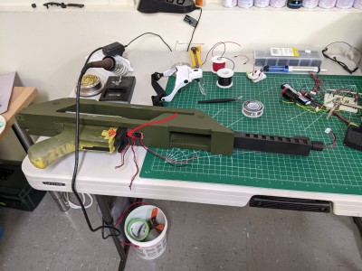
The upper shroud had three sets of wires coming out of it - the trigger, the on/off switch, and the muzzle LED. In the lower shroud I'd be adding the speaker and the battery power, and then it'd all be wired up to the Majenko counter & LED control board. As I'd been assembling sections and pulling wires through channels, I'd been using a multimeter to make sure my wiring was good.

But as I was about to start wiring up the Majenko Counter, I realised I couldn't remember if I'd tested the trigger, so I figured I'd double check and got out the multimeter. To my horror, I found that the trigger was physically working, but it wasn't closing the circuit. I tested & re-tested, making sure I was doing it all correctly, but still got the same result. I managed to get my multimeter prongs through the tiny gap to touch the switch contacts, and still wasn't getting any response from the switch.

Attachment:
BadSwitch.jpg
BadSwitch.jpg [ 636.1 KiB | Viewed 3669 times ]


To understand why this was awful, I've drawn an arrow to the hole through which I could see my switch, and a rough guess as to where the switch was inside the trigger housing. After kicking myself for not testing the trigger before I stuck the receiver on top (and followed it with the shroud), I took it over to my EE friend to see if he had any thoughts.

At the time, I assumed my problem was that my amateur soldering skills had screwed up one of the connections to the switch. I was hoping that my friend had some magical soldering iron that could work through the tiny gap. We examined it with his better tools, but he felt like the connections seemed solid (we weren't certain, as I'd wrapped them with heat shrink tubing). So his other guess was that perhaps the superglue I'd used had screwed me - he explained that superglue will off-gas vapour that hardens to a film afterwards, and can get through extremely thin gaps (of which there were some in the side of the switch). He thought it possible the film had deposited on the switch's contacts, and blocked them.

So I went back home and thought about it for a while. I couldn't see how to get around the fact that I had to be able to get at the switch to fix the problem, but at the same time I really, really didn't want to have to disassemble everything. I toyed with the idea of just abandoning the electronics on this build, and worrying about them on the next. Later that day, while I was in the process of whining to my wife about how much I'd screwed up my build, she suggested I try figuring out the least damaging set of cuts I could make to get at the switch.

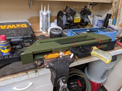
I spent some time staring at my model in Blender, and realised that she was onto something. Thanks to the way my model slotted together, I hadn't actually glued the shroud to the Thompson, nor had I glued the Thompson receiver to the trigger housing. If I could just get the shroud off, everything would just slide apart, and I could access the switch through the top of the trigger housing.

Attachment:
Gulp.jpg
Gulp.jpg [ 532.63 KiB | Viewed 3669 times ]


Here you can see the three cuts I made. I actually didn't need to make a fourth, because I found I could bend the thin shroud part out enough for the Thompson to slide out. It's possible I could have done it with just two cuts, I now realise.

As soon as I had access to the switch, I could see it was in a bad way, semi corroded/melted, I assume due to the interaction with the superglue. It pretty much fell apart into tiny pieces as I scraped it out. After that, I slotted in a new switch, and pinned it into place with a 3d printed cap, using no superglue whatsoever. I tested, retested, and tested again the connections with a multimeter before closing it all up again.

The cuts meant I now had small gaps between my pieces, so I used a technique my modelling buddy had suggested months earlier: glue together thin styrene sheets to fill up the missing gap, sheet by sheet, and then sand the sheet edges down to match the adjacent edge. I found this produced less visible connections than the bondo putty smoothing I'd been doing, so I might try to do this with all my connections in the future.

After I was done repairing them all, I had to repaint most of the shroud again, redoing my weathering pass. A week later, I was back to being ready to finish up the electronics, and breathing a sigh of relief when all my connections were green across the board.


Top
 Profile  
Reply with quote  
 Post subject: Queen To Bishop
PostPosted: Wed Aug 04, 2021 4:52 am 

Country: United States
After a couple of hours, I had everything wired up. I did all the testing I could figure out how to do with my multimeter, before realising I had to turn it on. I still remembered how I'd burned out the muzzle LED back when I built a test circuit.

Attachment:
CircuitMess.jpg
CircuitMess.jpg [ 306.22 KiB | Viewed 3669 times ]


It turns out my instinct was correct, because the second I plugged in the battery there was a puff of smoke and a smell of electrical things burning. I immediately unplugged it, and spent the next 30m trying to figure out what I'd done wrong. I went over the whole circuit, and it all looked correct, and whatever connections I could test with the multimeter showed as being good. I gave up and asked my EE buddy to come take a look when he had time.

A few days later he arrived with a bunch of equipment, including a linear power supply with the ability to control the current. Armed with that, we went over the circuit until we'd determined that the Majenko counter circuitboard itself was toast (likely due to me doing Something Bad way back when I was fumbling my way through a test circuit). I had a second one to compare against, so we swapped that for the burned one.

Using the power supply instead of the battery, we were able to safely test power flow through the circuit, and found that I had actually managed to wire everything up correctly.

https://drive.google.com/file/d/1kxd3hPelrL6jrMlR1GkjpFRTkTWskrlu/view?usp=sharing

It took a bit of work to get the lower shroud onto the upper shroud without crushing any of the electronics. I ended up needing to rewire it all again with shorter wires, but was a bit trapped by the way my design required enough length in the wires to remove the lower shroud when I need to replace the battery. I've just recently bought a couple of plugs, and my intention is to rewire it yet again, but this time with a single plug that connects all the upper shroud wiring to the lower shroud's, so that this is cleaner & less prone to breakage.

The last electronic bit I wasn't that happy with was the reed switch I used to detect the magnet inside the magazine (telling the Majenko counter when the magazine has been inserted). I used hot glue to stick the reed switch in place, but the location it needs to be to detect the magnet turns out to be a bit too close to where the upper shroud slots onto the lower. As a result, the reed switch keeps getting moved when I pull the shrouds apart. Definitely want to improve that on the next one.

With all the electronics finally working, I suddenly realised I was almost done. All I had to do now was to finish painting all the pieces, and attach them. For the first time ever, I felt like I could see the end of my build in sight, and I started painting as fast as I could.


Top
 Profile  
Reply with quote  
 Post subject: Resolution And Hyperspace
PostPosted: Wed Aug 04, 2021 5:07 am 

Country: United States
And I was finally done with my oversized PR.

Attachment:
FinallyDone1.jpg
FinallyDone1.jpg [ 623.15 KiB | Viewed 3668 times ]

Attachment:
FinallyDone2.jpg
FinallyDone2.jpg [ 574.98 KiB | Viewed 3668 times ]

I was planning on taking some extra photos before I posted all this, including ones of the lit up counter, and then the electronics broke as I futzed around taking the shroud off for one last check. So I've picked up some electronics to redo the wiring properly. Once I've done that I'll take some better shots of it from other angles.

I hope that this has been an entertaining read. If you haven't built one of these, I hope my clear lack of experience helps you realise that you can do it too, and that you'll likely make fewer mistakes than I did. To be honest, if you've found this forum before you've started, you're already ahead of me.

If I had to pick the one mistake I repeated most often throughout my build, it was that I always started doing stuff before I'd spent the time really researching what it was I needed to do. This was the root cause of much of my modelling inaccuracies, my assembly troubles, my paint color failures, and my big mistake during printing.

That said, I think there is a balance to be struck between research / planning, and doing. I find that my initial excitement about building always starts to wane as my research / planning reveals the mountain of work ahead of me, and all the things I don't know / understand. If I spend too long in that space, my momentum peters out and I never manage to get to building anything at all.

Anyway, thanks for reading my build thread!

Robin.


Top
 Profile  
Reply with quote  
 Post subject:
PostPosted: Wed Aug 04, 2021 12:20 pm 
User avatar

Location: Portsmouth
Country: United Kingdom
Well first of all, well done! And thank you for posting such an in-depth and descriptive account of your build.

Oddly your story is almost identical to mine in so many ways!
Prusa i3 Mk3 purchased just before lockdown, decision to make a PR (mine came after I finished an M56 smartgun but that's another story!), dissatisfaction with the existing free models so a rebuild/modify effort based on a few of them using Blender, the discovery of the Majenko kit and the integration of that into the build, even down to painting it olive drab (I used Humbrol rather than Tamiya) as I figured that was a close colour to the way it appears in the majority of the film.
I think the only things I did differently was to mount the speaker in the front of the shroud and my on/off switch (an identical one to yours!) is revealed in a recessed hole underneath the spas cage when you slide back the pump grip!
Oh and I do rather like your magazine clips, I embedded neodymium magnets in the base of the mag well and the mag base for ease but your clips are a lot more "authentic"


Top
 Profile  
Reply with quote  
 Post subject:
PostPosted: Wed Aug 04, 2021 12:31 pm 
User avatar

Country: Australia
Really great read - Don't worry, you never stop improving your design. That's just version 1.... soon you will have version 3 on the printer.....

_________________
FB:
https://www.facebook.com/99rivingtonst

Cults:
https://cults3d.com/en/users/PaulsBoutique/creations


Top
 Profile  
Reply with quote  
 Post subject: Re:
PostPosted: Thu Aug 05, 2021 3:49 pm 

Service Number: A05/TQ2.0.32141E1
Country: United States
PaulsBoutique wrote:
Really great read - Don't worry, you never stop improving your design. That's just version 1.... soon you will have version 3 on the printer.....


Once you get it functional, please post a parts list, or get a parts list and coding of what you are using now as we would all like to copy this functional design.

_________________
The impossible takes a while longer and goes over budget too...


Top
 Profile  
Reply with quote  
 Post subject: Re: The Complex
PostPosted: Thu Aug 05, 2021 9:00 pm 
User avatar

Country: United States
Robin wrote:
Attachment:
Circuit.jpg


At first, this turned out to not be as hard as I was expecting. Majenko provides a nice diagram, I watched some refresher tutorials, and managed to get it working. But somewhere in the process of testing stuff I burned out the muzzleflash LED. Looking at the Majenko page again, I saw that it asked you to tell them what size resistor you wanted on the LED, but I hadn't done that. Did that mean there wasn't a resistor on it?

I wasn't sure, but if there was no resistor, and my math was right, I should have a 13 ohm resistor near the LED. I ran all this by a friend who's an EE, and he agreed it was worth doing. At worst, if it wasn't necessary I'd just have a muzzle flash that wasn't quite as bright. He gifted me some 25 & 27 ohm resistors to use in parallel, and I moved on.

Much later, during final assembly, I'd find that I'd burned out the board on the Counter itself, and that perhaps LED had been fine all along.

Attachment:
SpeakerAndSwitch.jpg


The speaker I'd used in my test circuit was too big, so I went hunting for a smaller one that I could fit into some part of the shroud. I figured it'd be best if the speaker faced forward, so that it projected towards the target. The most obvious place seemed to be the curved part of the lower shroud, and sure enough, I was able to find a speaker that fit in there. I modelled a small grille for it, and a channel for wiring to run back and and up to the Majenko counter.

(The highlighted orange bits in this pic are the blockout for the speaker itself, so I could see what to build around)

Attachment:
Speaker.jpg


I wanted to hide the on/off switch somewhere, because I couldn't find some existing part of the PR design that looked like it could be faked as. I briefly toyed with the idea of re-using the safety, but that looked like it was going to be too small / delicate a piece for use as a switch. I thought the best place to hide it would be under the stock at the back of the Thompson. I found a black rocker switch that fit perfectly at the end of the Thompson, set flush so it's hard to even spot it even without the stock.

Attachment:
OnOffSwitch.jpg


This meant I had to hollow out a channel all the way through the Thompson receiver, so wiring could run from the switch to the Majenko counter.

Next up was the battery.
so you made the board? Who's Majenko? Looks great currently making a fully mechanical pr 3d printed. How much did it cost to make the electronics.


Top
 Profile  
Reply with quote  
 Post subject:
PostPosted: Thu Aug 05, 2021 10:54 pm 
Marine Raider
User avatar

Location: Pontyrhyl
Service Number: A05/TQ2.0.92155E1
Country: United States
Wow what a cool PR. Great work :))


Top
 Profile  
Reply with quote  
 Post subject:
PostPosted: Fri Aug 06, 2021 3:12 am 

Country: United States
Majenko Technologies is the UK company that I bought the PR Counter and LED kit from. It looks like the version I used has now been supplanted by a better one that combines it all into one thing: https://majenko.co.uk/aliens-m41a-pulse-rifle-counter
That new one is smaller, and looks easier to wire up.

The cost of the three options are on the Majenko page. Beyond that, the electronics I used were these (all prices in USD):
- 3A Microswitch W/Lever ($2.49)
- 2S LiPo Battery ($26.95)
- Reed switch ($3.59)
- Magnet (set of 4 $4.99)
- SPST Waterproof Rocker switch on-off 20a ($4.24)
- Assorted wires, molex plugs, heat shrink tubing, solder, etc.

For the springs used in the mechanical pieces, I just bought a small set of variably sized springs at Home Depot. I think it was less than $10.

Robin.


Top
 Profile  
Reply with quote  
 Post subject:
PostPosted: Fri Aug 06, 2021 3:20 am 

Country: United States
Oh, sorry, I forgot to include some other bits:
- Majenko's LED driver board (£4.00) : https://majenko.co.uk/shop/led-driver-board-24
- Majenko's 10mm Aluminium mounted Cree LED (£4.00) : https://majenko.co.uk/shop/10mm-alumini ... ree-led-25
- Speaker (I used Majenko's £3 one here, but you don't have to) : https://majenko.co.uk/shop/5w-8-ohm-spe ... 70x17mm-23

Robin.


Top
 Profile  
Reply with quote  
 Post subject: Re:
PostPosted: Fri Aug 06, 2021 3:02 pm 
User avatar

Country: United States
Robin wrote:
Majenko Technologies is the UK company that I bought the PR Counter and LED kit from. It looks like the version I used has now been supplanted by a better one that combines it all into one thing: https://majenko.co.uk/aliens-m41a-pulse-rifle-counter
That new one is smaller, and looks easier to wire up.

The cost of the three options are on the Majenko page. Beyond that, the electronics I used were these (all prices in USD):
- 3A Microswitch W/Lever ($2.49)
- 2S LiPo Battery ($26.95)
- Reed switch ($3.59)
- Magnet (set of 4 $4.99)
- SPST Waterproof Rocker switch on-off 20a ($4.24)
- Assorted wires, molex plugs, heat shrink tubing, solder, etc.

For the springs used in the mechanical pieces, I just bought a small set of variably sized springs at Home Depot. I think it was less than $10.

Robin.

Are you in the uk or did you import all this? You'd think these parts would be available in the US also.


Top
 Profile  
Reply with quote  
 Post subject:
PostPosted: Fri Aug 06, 2021 5:15 pm 

Country: United States
I'm in the US. I imported the Majenko pieces, but everything else was just from a local electronics shop.

Robin.


Top
 Profile  
Reply with quote  
 Post subject:
PostPosted: Fri Aug 06, 2021 8:44 pm 
GarageGeek
User avatar

Country: United States
This is pure inspiration. Can you recommend a way to learn 3D design like this?


Top
 Profile  
Reply with quote  
 Post subject: Re:
PostPosted: Sat Aug 07, 2021 12:11 am 
User avatar

Country: United States
Robin wrote:
I'm in the US. I imported the Majenko pieces, but everything else was just from a local electronics shop.

Robin.

So that site sells kits to build? Also how hard is it to add the sound efx?


Top
 Profile  
Reply with quote  
 Post subject: Re:
PostPosted: Sat Aug 07, 2021 3:44 am 
User avatar

Country: United States
Robin wrote:
I'm in the US. I imported the Majenko pieces, but everything else was just from a local electronics shop.

Robin.
thanks for sharing btw. I just paid 190 dollars for a pre-made electronics rig. Whole time wondering if I can make them.... Appreciate you.


Top
 Profile  
Reply with quote  
 Post subject: Re:
PostPosted: Mon Aug 09, 2021 11:23 pm 

Country: United States
seven wrote:
This is pure inspiration. Can you recommend a way to learn 3D design like this?

Blender is a great modelling tool, and it's open source and free. There are tons of tutorials for it out there.

https://www.youtube.com/watch?v=TPrnSACiTJ4 is a famous one that you follow along with while it teaches you. But it covers a ton of things you don't actually need to know, because luckily for us, if we're just modelling something to 3d print, there are tons of things we don't have to worry about (like texturing/UVs/rendering/etc). So we'd only have to learn part 1 of this 4 part series.

In the end I watched this other guy's tutorials, which were more focused on modelling shapes vertex-by-vertex. I think I only followed along with a couple of his episodes before I felt I was being productive: https://www.youtube.com/watch?v=Hf2esGA7vCc

As a bonus, the Pulse Rifle isn't actually that complex (compared to a human, for instance). With some good reference images as the background behind your modelling, it's a bit like tracing.

Spend a couple of hours on it, and see how you go. I wasn't expecting to enjoy it when I started, but in the end I loved it.


Top
 Profile  
Reply with quote  
Display posts from previous:  Sort by  
Post new topic Reply to topic  [ 28 posts ]  Go to page 1, 2  Next


You cannot post new topics in this forum
You cannot reply to topics in this forum
You cannot edit your posts in this forum
You cannot delete your posts in this forum
You cannot post attachments in this forum

Search for:
Jump to: