Links to parts.
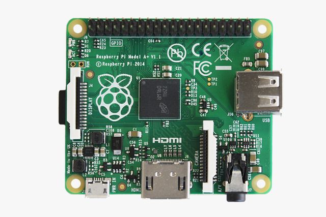
Controller Raspberry pi A+.
http://uk.rs-online.com/web/p/products/8332699/Must be the type a+
TFT display.
http://feeldo.net/products/139-digital- ... ensor.aspxebay seller.
http://www.ebay.co.uk/itm/231729993983? ... EBIDX%3AIT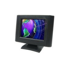
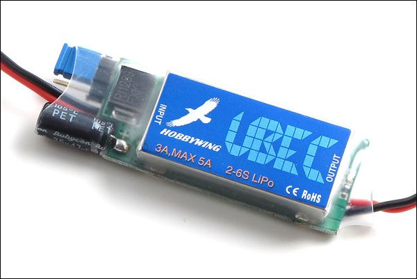
UBEC. loads on ebay just search UBEC.
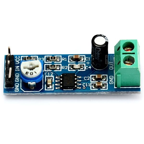
Amp board.
ebay search lm386 200 gain.
Speaker.
http://www.maplin.co.uk/p/025w-mylar-sp ... 56mm-vc85g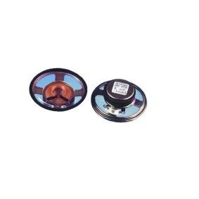
switches for slide viewer.
http://uk.rs-online.com/web/p/slide-switches/0337497/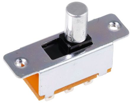
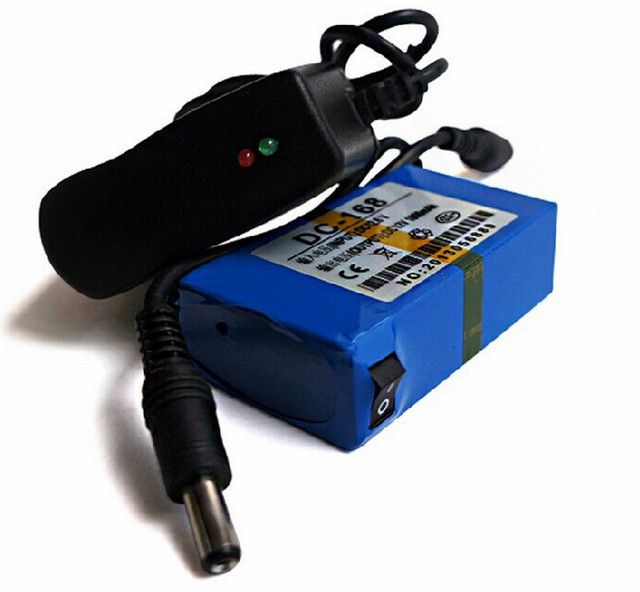
battery. I used a dc 168 battery. battery with charger from ebay search dc 168 battery
My raspberry pi image.
https://mega.nz/#!kZkCDLiI!GvTFYrx9XyxW ... m1_FTvuLxQTutorial.
Step 1:
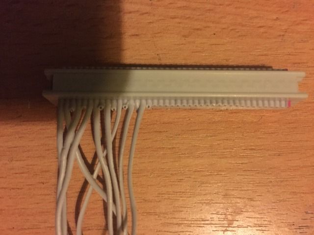
We will start by preparing the ide cable.
1: The cable will come with a multi pin plug on both ends. Cut the cable in half. So you now have 2 multi pin plugs.
2: Now place the ide cable on a table, with the plug away from you and wires facing towards you. All the pin holes facing the table.
3: Working from left to right.
4: Tear each wire from the cable next to it. Pull it all the way down to the multi pin plug. Starting with the first on the left (number 1)
5: Now repeat pulling back wires to multi plug. 2 then 3 then 4 all up to 16.
6: Any wires to the right after counting 16 are not required. So from 17 on wards cut them flush with the multi plug. (wire now to your right)
7: We now remove a few of the 16 wires you have left.
8: From left to right
9: wire 1 keep, wire 2 keep, wire 3 will be removed so cut it back to multi block. wire 4 keep, wire 5 remove as you did for wire 3. wire 6 keep, wire 7 keep, wire 8 remove, wire 9 keep, wire 10 remove, wire 11 keep, wire 12 remove, wire 13 keep, wire 14 remove, wire 15 keep, wire 16 keep.
So you should now have 10 wires left.
From now on wires will be counted 1 to 10 from left to right.
Should look like this but you will have 1 extra wire. Number 16.
Step 2:
From now on wires will be numbered 1 to 10 from left to right.
1: Cut all the wires to about 3 inch long.
2: wire 1 now needs a resistor adding to the end of the wire. Strip part of plastic covering away. And solder resistor to wire. 270Ω (ohm) resistor
3: Now count from wire 1 to wire 8. wire 8 will need a resistor adding. 270Ω (ohm) resistor
4: now solder aprox 6 inch of wire to the end of both resistors. And cover the resistor in heat shrink (NO BARE CABLE EXPOSED)
This is the feeds for the red and green led`s
Step 3:
Connecting the wire to the lm386 amp.
1: The board as 4 pins to the left.
2: Bottom pin (GND) solder 4 inch of black wire to the pin.
3: Next pin up (GND) solder 4 inch of wire to the pin. ( i used brown ) but up to you.
4: next pin up (IN) solder 4 inch of wire to the pin. ( i used purple ) but up to you.
5: Final pin (ACC) solder 4 inch of red wire to the pin.
6: Cover all 4 soldered areas with heat shrink.
Step 4:
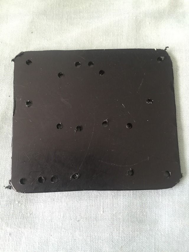
Plastic mounting plate.
1: Get a bit of plastic.
2: And place the raspberry pi on the plastic.
3: Draw around the raspberry pi.
4: now cut out the shape.
5: now place raspberry pi back on the plate.
6: mark and drill the 4 outer holes that are on the raspberry pi onto the plastic plate.
Step 5:
Mount the amp and ubec to the plastic plate.
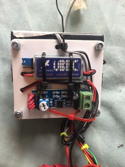
Then drill some holes and cable tie the items in place.
Step 6:
The UBEC.
1: The ubec has input and a output.
2: (input) this will be the the feed from the battery.
3: (output) this will be the feed to power up the items.
Step 7:
1: Now cable tie the plastic board to the back of the raspberry pi.
2: Plug the ide cable onto the raspberry pi, with wires running down the board.
3: The output wire from the UBEC run it tidally around to the ide cable wires.
4: The RED wire output from the UBEC now needs soldering to the ide cable number 2.
5: The black wire output from the UBEC now needs wrapping around ide cable number 4. Do not solder yet.
6: Now the RED wire from the AMP board run it tidally around to the ide cable wires.
7: Solder the red wire to ide cable wire number 3.
8: Now the BLACK wire from the AMP board run it tidally around to the ide cable wires. And wrap the wire around ide cable wire number 4 (you should now have 2 wires ready to solder)
9: Now solder the wires in place. And cover soldered area using heat shrink.
10: Now solder 6 inch of any colored wire to ide cable wire number 5 (i used white)
11: Now solder 6 inch of BLACK colored wire to ide cable wire number 6
12: Now solder 6 inch of any colored wire to ide cable wire number 7 (i used white)
13: Now solder 6 inch of any colored wire to ide cable wire number 9 (i used white)
14: Now solder 6 inch of any colored wire to ide cable wire number 10 (i used white)
Wire numbers 5/7/9/10 will trigger videos. wire 6 is ground. Add a bit of tape to the wires and put the correct number on it for reference.
Step 9:
1: You now have 2 wires left on the amp board, i used brown and purple.
2: Run both the wires around to the 3.5 mm headphone jack on the raspberry pi.
3: Cover up surrounding area using tape.
4: solder the two wires in place.
5: Now get 6 inch of yellow wire, strip the end off and solder the wire end.
6: Now feed the yellow wire threw the back end of the 3.5mm jack, till it pokes out the front of the 3.5mm jack housing.
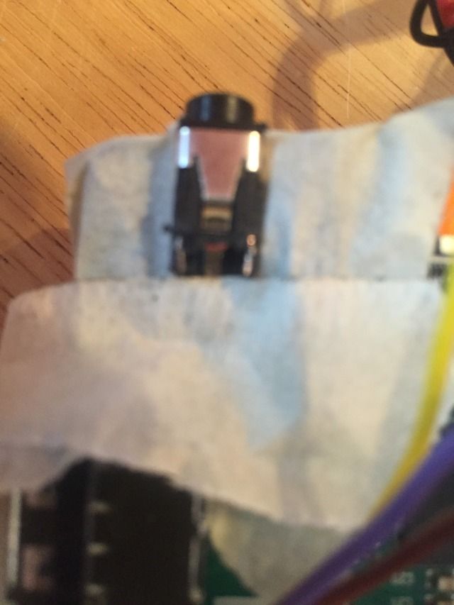
7: The yellow wire needs soldering to the video feed. it`s on the bottom you should see the metal plate in the jack hole.
8: Get the yellow soldered wire hot and pull wire back into jack housing it should solder to the video plate in the jack housing.
Now test to see if its working.
Insure now bare wires are touching the boards or wires touching each other.
The UBEC input wires red and black connect them to your battery supply. Make sure you get the red and black correct way round. You should now have the led on the UBEC lighting up, the led on the amp board. And a green and red small led on the raspberry pi.
Step 10:
Copy my image to a memory card.
1: Download my image from here.
https://mega.nz/#!kZkCDLiI!GvTFYrx9XyxW ... m1_FTvuLxQNote: It`s a 8 gig image so may take a long time to download.
2: Download the tool to burn the image once downloaded.
http://sourceforge.net/projects/win32di ... p_redirect3: Connect your memory card to your P.C.
4: how to use win32diskimager
Using Win32DiskImager
1: Having plugged in your SD card, (re)start Win32Diskimager. Choose the drive you want to copy the image to (in my case F: ).
2: Choose the drive with your SD card to write the the image on
3: Then click on the folder icon and choose the image (final build 4 triggers.img) Then click Write, to write my image on to the card.
4: Then click Write file to SD card
5: You will then be asked to confirm. Check carefully that you are writing to the correct device and if so, click Yes.
6: Check device and confirm
The progress bar will show you how far it’s got.
Finished

Your image is now ready to put into your raspberry pi.
you should be able to find and insert the memory card into the raspberry pi.
At this point you can plug a hdmi cable into the raspberry pi and connect it to your tv in the living room.
Connect a battery again and you should shortly see this logo on the bottom right of your tv.

From what i remember it will be upside down and have no sound. don't worry this is due to how i rotated the screen image and forced sound to the 3.5mm jack.
After the boot screen you will see the static image.
Now if you want you should have 4 wires any colour i said you could use (i used white). Video triggers, expose a tiny bit of wire, now hold it on the metal outer body of the usb port. (NOT the RED wires there are led feeds) you will now see the video.
Step 11:
The tft display.
You should have received a display by now, so lets strip it down.
1: you should see on the rear body there are 4 screw holes, remove them screws.
2: Now you should be seeing the display board and back of the tft display. It may be glued or screwed in place.
3: Remove the display by removing the glue or the screws.
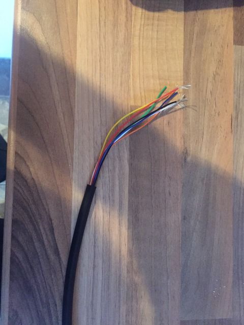
4: Cut the plug off just before it splits into 2 cables. you will now be able to remove the plastic body from the cable.
5: Now strip the cable to reveal the wires inside. you will have red/white/black.
Step 12:
Connecting display to the raspberry pi.
1: Connect the red and black wires to your battery. (test fit)
2: You should have that yellow wire coming from the 3.5 jack on the raspberry pi. Connect that yellow wire to the white wire from the tft display.
3: Now connect the battery to the raspberry pi as you did before.
You will now be seeing the image on the display.
Step 13:
The speaker.
1: The speaker has + and -
2: Solder about 12 inch of wire to the speaker terminals.
3: On the amp there is 2 speaker connectors using screws.
4: Put the wires from the speaker to the amp + and -(- is the lower one) + is the top one.
5: turn tiny volume knob on the board.
You now have sound.
Whats next ?
You now have working electronics, this all needs fitting inside the motion tracker.
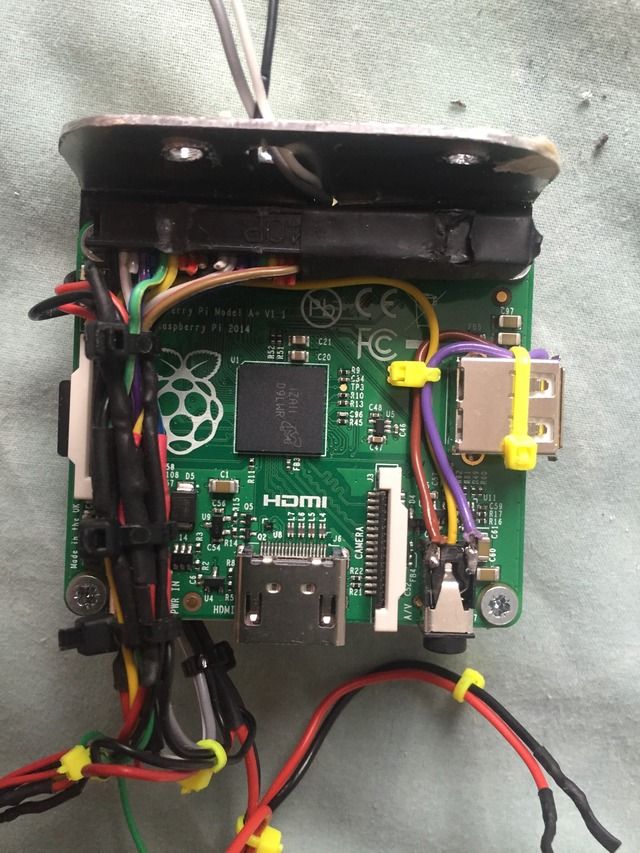
Inside mine is set up like this.
raspberry pi and battery sit in the top section of the kango. (i used my dremel to remove the 4 unused screw fixings for extra room)
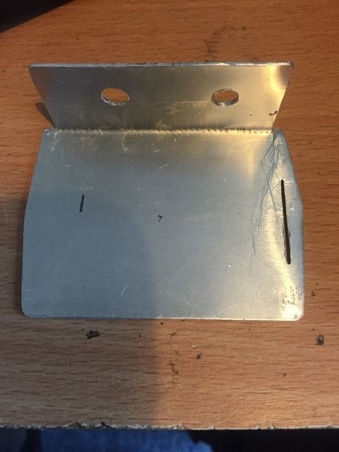
And i made a alloy plate to fix my raspberry pi to the kango. and see on off switch. top right.

The black tube i used to join the kango to slide viewer. I feed 7 wires inside the tube. So display from raspberry pi, led feeds and one video trigger.
I fitted a external on off switch that just breaks my battery + feed.
My battery is charged via this.
Screen inside the slide viewer.
I made a alloy plate to fit all my parts to. The real working switches leds, and the tft display.
fitted parts.
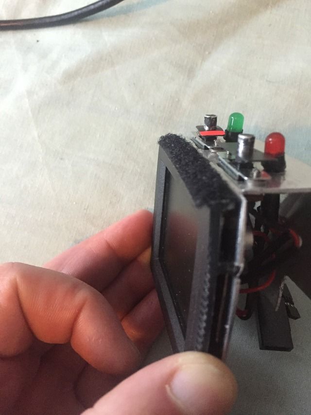
my viewer removable case is flat inside to allow the switches and leds to sit correctly.

The metal plate fits in the groves in the original viewer and the display fixed to the front of the plate.
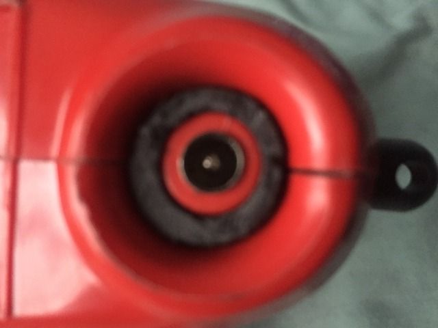
My speaker is mounted in the kango lower section, the part here the bushes where fitted behind the removable doors.


 AKA: Simon